Back to projects

Metal Detector

A metal detector built from discrete MOSFETs on a custom Altium PCB. It cascades stages of two LC oscillators, a mixer, a low pass filter, and a source follower that interfaces with the speaker.

ESE 3190 · UPenn Spring 2026 Altium LTspice Analog Design
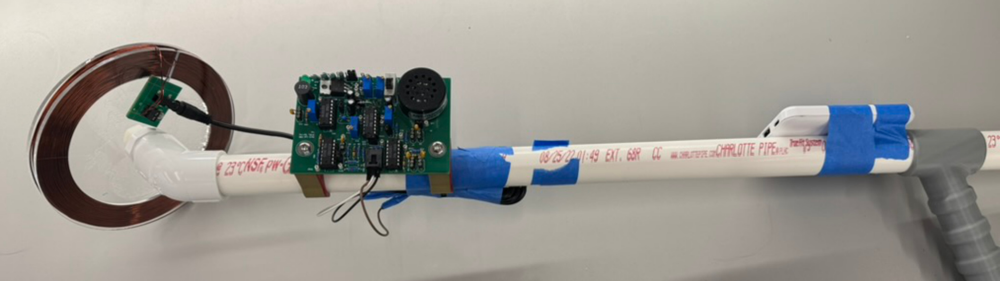
The finished metal detector: a hand-wound copper coil with the custom PCB and speaker mounted to the shaft.
The finished build, with the hand-wound 5.36 mH inductor coil and the custom PCB and its speaker mounted to the shaft.

How it works

General overview

The metal detector works by cascading stages of two LC oscillators, one custom and one fixed, along with a mixer to add the two signals. This mixer is followed by the 1st CS amplifier, which generates a differential signal due to the square law of current of a MOSFET. Then, the low pass filter filters out the higher frequency signals, leaving only the differential signal of the two LC oscillators, which are 50 kHz and 49 kHz, producing a 1 kHz differential signal. This is then boosted by a 2nd CS amplifier, which is fed into the source follower that interfaces with the low resistance speaker.

The way the metal detector actually detects metal is by inducing eddy currents in nearby metal, which in turn lowers the inductance of the custom inductor. Lowering the inductance raises the frequency that the custom LC oscillator passes, so the differential signal of around 1 to 2 kHz shrinks, producing a lower pitch sound.

Stage 01
Two LC oscillators
49 & 50 kHz
Stage 02
Mixer + 1st CS amp
adds the two signals
Stage 03
Low pass filter
fc = 7.23 kHz
Stage 04
2nd CS amp
extra gain
Stage 05
Source follower
interfaces with speaker
Oscillators

I wound up the inductor coil until I achieved an inductance value between 5 mH and 10 mH, ending up with 5.36 mH. This range was chosen because anything above 10 mH would take too large of an inductor coil, while an inductor that is too small would require a very large capacitor to maintain a resonant frequency of 49 kHz, which would take up excess space on the PCB. A small inductor also generates a small magnetic field, so the eddy currents induced in the metal would be small as well, leading to only a small change in inductance and an insensitive metal detector. Using f = 1/(2π√LC), the custom capacitor came out to 1.96 nF for 49 kHz, and the fixed oscillator used a 10 mH inductor with 1.01 nF for 50 kHz.

Mixer

The mixer uses a differential amplifier topology to add the two oscillator signals together. Since both inputs sit on the inverting input of the differential amplifier, the theoretical gain works out to −10 V/V. The first common-source amplifier then amplifies the result into a 2 kΩ load, and because the current of a MOSFET follows a square law, this stage is what generates the differential signal.

Filter

Assuming a perfect 1 kHz differential signal, I wanted a low pass filter capable of attenuating the higher 49 and 50 kHz frequencies while passing the 1 kHz differential frequency. Using f = 1/(2πRC) and the values available in the Detkin laboratory, I settled on a 10 kΩ resistor and a 2.2 nF capacitor, which gives a cutoff frequency of 7234 Hz. The 10 kΩ resistor was a good choice because this filter connects directly to the output of the mixer's CS amplifier, which has a load value of 2 kΩ. Choosing a resistance significantly larger than 2 kΩ prevents loading, where the gain drops because the total equivalent resistance to AC ground drops.

Output

The primary purpose of the 2nd CS amplifier is to provide some extra gain, creating a larger sound for the metal detector. A 2.2 kΩ resistor was a good choice here since it is large enough to provide noticeable gain while not being so large that it pushes the transistor out of saturation. The signal then goes into a source follower. Attaching the low resistance speaker directly to a CS amplifier would not work, because the CS amplifier has a large output resistance looking into the MOSFET. If we think about the CS amplifier output as a Thévenin equivalent, the Thévenin resistance would be large, so the speaker would only get a small portion of the voltage drop. The source follower solves this since its output resistance is much lower, which gives the speaker a much better voltage transfer.
Design & hardware

Schematic details

The component values below came out of the resonant frequency and RC cutoff equations. As for biasing, I decided to bias most of the PMOS and NMOS at a gate voltage of 3 V for the sake of consistency, since 3 V is a good middle ground between 0 V (ground) and 5 V (VDD). This ensures that the gate to source voltage for both the PMOS and NMOS is large enough to pass current while remaining in saturation. Too small of a gate voltage would turn the NMOS off, and too large of a gate voltage would put it in triode. These voltages were tuned with the potentiometers and measured with a voltmeter.

ParameterValueWhy
Search coil5.36 mHWound by hand, large enough to induce eddy currents in nearby metal
Variable osc. cap1.96 nFResonates the coil at 49 kHz
Fixed osc.10 mH / 1.01 nFFixed reference frequency at 50 kHz
Low pass filter10 kΩ / 2.2 nF7234 Hz cutoff, large enough to avoid loading the 2 kΩ stage
2nd CS amp load2.2 kΩNoticeable gain without pushing the transistor out of saturation
Gate bias3.0 VA middle ground between ground and VDD that keeps the devices in saturation
Tail current bias1.141 VGate voltage of the NMOS current mirror that supplies the tail current
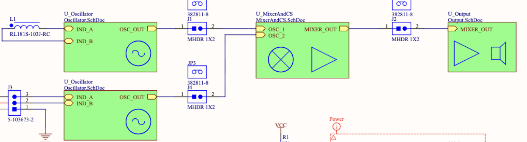
Top-level Altium schematic showing the two oscillator sheets feeding the mixer and output stages.
The top level Altium schematic. Both oscillator sheets feed into the mixer and CS block, which then drives the output stage and the speaker.
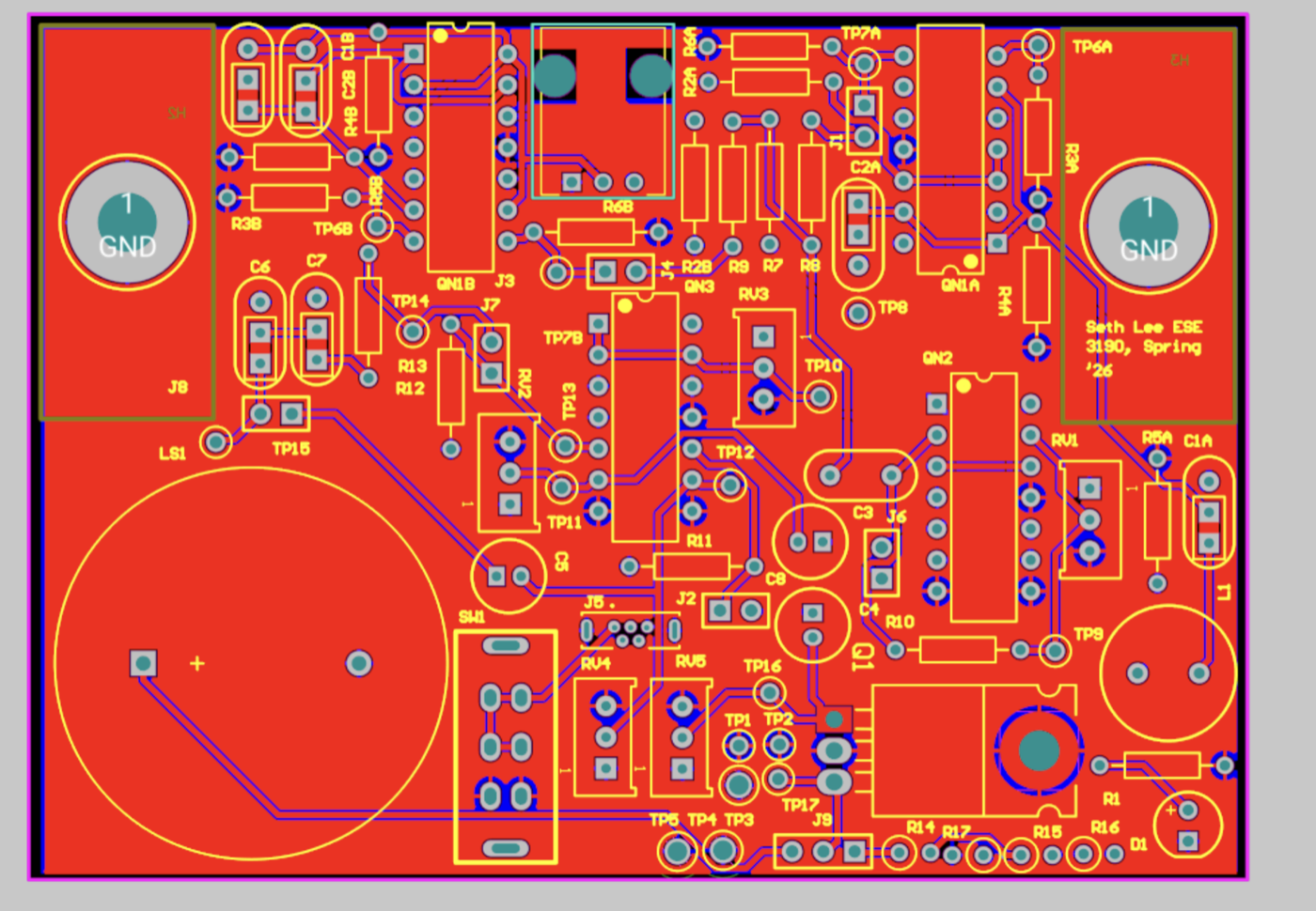
Altium PCB layout of the metal detector board.
The PCB layout. Test points TP1 through TP17 were placed so that every stage could be probed on a powered board, which is how the measurements below were taken.

Measured results

Oscilloscope waveforms

To measure the various stages of the metal detector, I first powered it on to ensure that its stages were on, since MOSFETs are active circuit elements. Then I used the red and black probes from the oscilloscope to measure each of the stages using the test points, with the red probe attached to the test point and the black probe to ground.

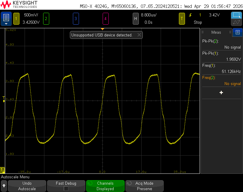
Oscilloscope capture of the fixed oscillator.
Fixed oscillator (TP7A). Measured at 51.1 kHz and 1.96 Vpp. It was not exactly 50 kHz due to parasitic inductances and capacitances, as well as the tolerance of the capacitors and inductors.
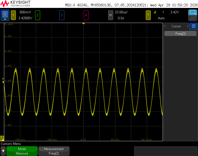
Oscilloscope capture of the variable oscillator.
Variable oscillator (TP7B). Measured at 49.1 kHz from the hand-wound coil, which is close to the 49 kHz that it was designed for.
Oscilloscope capture at the mixer output.
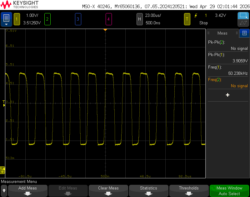
Mixer (TP8). Measured at 50.2 kHz and 3.91 Vpp. This is the wave once the two oscillator frequencies are mixed together.
Oscilloscope capture at the first common-source amplifier.
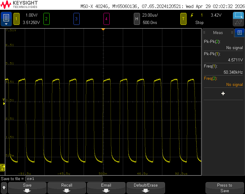
1st CS amplifier (TP13). Measured at 4.57 Vpp. This stage boosts the peak to peak voltage of the signal since it has gain, and it also introduces the differential signal.
Oscilloscope capture after the low-pass filter.
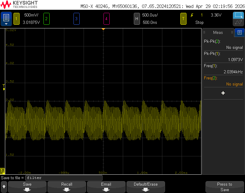
Low pass filter (TP15). The higher frequencies are attenuated while the lower differential frequency is passed, leaving a 2.04 kHz signal at 1.097 Vpp.
Oscilloscope capture at the second common-source amplifier.
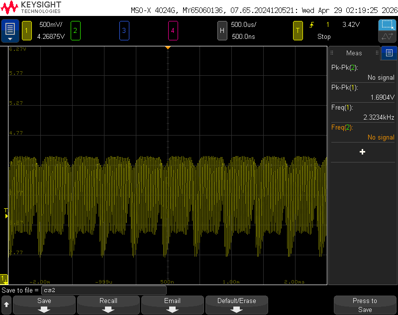
2nd CS amplifier. Measured across the ungrounded side of the 2.2 kΩ load. The differential signal is boosted from 1.097 Vpp to 1.690 Vpp, allowing the speaker to produce a louder sound.
Oscilloscope capture at the source-follower output stage.
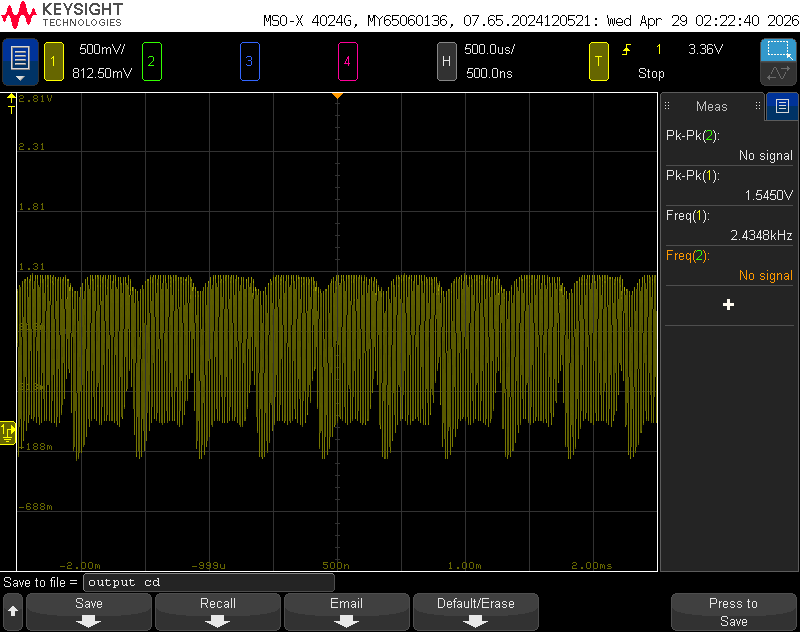
Output stage (TP17). Measured at 2.43 kHz and 1.545 Vpp into the speaker. The common drain stage ideally has a gain of 1, but in reality attaching a very small output resistance lowers the gain slightly.

Consistent with these oscilloscope screenshots, the metal detector worked in real life and was able to detect all of the objects on demo day. As the custom inductor came into contact with metal, the frequency of the variable LC oscillator changed, which shrank the differential signal and lowered the pitch of the sound coming out of the speaker.